


AF is the most common sustained cardiac arrhythmia in clinical practice. It is associated with increased risk of stroke and heart failure and is a significant global health challenge.1 Catheter ablation procedures, which isolate the pulmonary veins (PV) from the left atrium (LA) and prevent AF initiation, are effective and safe treatment options. They have emerged as the preferred rhythm control strategy for symptomatic paroxysmal AF that is refractory or intolerant to at least one antiarrhythmic medication.2,3
Catheter ablation of AF is the most common technique and is now the most commonly performed catheter ablation procedure. PV isolation (PVI) has become the standard of care in paroxysmal AF therapy.4 This procedure is associated with a high success rate (>70%) in paroxysmal AF, but with persistent AF the success rate remains low at around 50–60%.1 Success rates exceeding 70% are possible with better techniques, workflow and technological options, with some studies reporting up to 90% success rates.5–8
Despite advances and growing experience in percutaneous catheter ablation for AF, long-term outcomes for persistent AF are inferior to those for paroxysmal AF.4,9–12 High numbers of patients with persistent AF return to hospital and additional substrate ablation is frequently performed.13 Scar tissue is present in many of these patients, particularly in those with persistent AF but is also seen in those with paroxysmal AF. This scarring is associated with poor outcomes after PVI.14–16 This has led to the development of ablation strategies to eliminate low-voltage regions caused by scarring within the LA. This article aims to discuss the challenges of atrial scarring in patients with persistent AF and substrate mapping strategies for optimising the ablation of atrial scarring.
The Challenges of Atrial Scarring
Understanding the AF substrate is essential to improving outcomes in catheter ablation of patients with persistent AF and can enable individualised treatment approaches.17,18 A growing body of evidence indicates that pre-existing or iatrogenic atrial fibrosis, or scarring, plays a role in the maintenance of AF.19 Animal studies have shown that propagation of fibrillation waves is promoted by endocardial bundles in acute AF and by epicardial bundles in persistent AF.20 Atrial fibre bundle rearrangement results in more perpendicular orientation of epicardial to endocardial bundles, causing endo-to-epicardial dissociation of electrical activity and the formation of a 3D AF substrate.20 However, while the definition of ventricular scar is well established, this approach has been more challenging in the atrium because of the structure of the atrial wall and the great difficulty of detecting atrial fibrosis with existing imaging techniques.21
Atrial fibrosis can separate cardiomyocyte bundles, which can hinder electrical coupling and slow electrical conduction.22 The presence of scarring in the LA in patients with AF has therefore been associated with an abnormal electroanatomic substrate causing lower regional voltage, increased proportion of low voltage, slowed conduction, and an increased proportion of complex signals compared with controls.16 In a study of 700 consecutive patients undergoing PVI for the first time, pre-existing LA scarring was a strong independent predictor of procedural failure and was associated with a lower ejection fraction (EF), larger LA size, and increased inflammatory markers, with patients experiencing LA scarring having a significantly higher AF recurrence (57%) compared with patients without scarring (19%; p=0.003).14 In a multicentre, prospective, observational cohort study of patients diagnosed with paroxysmal and persistent AF undergoing their first catheter ablation with PVI, atrial tissue fibrosis estimated by delayed enhancement MRI (n=272) was independently associated with the risk of recurrent arrhythmia.15
A promising new strategy for ablation of AF is atrial scar-based catheter ablation to modify low-voltage regions that may indicate scarring and/or zones of non-uniform anisotropic conduction within the LA and convert them into electrically silent regions.18,23,24 In a study that compared the 2-year outcomes in patients with paroxysmal AF and severe LA scarring identified by 3D mapping who were undergoing PVI only or PVI plus scar homogenisation, the latter group had significantly better long-term outcomes than PVI alone. While single procedures had a low success rate, ablation of non-PV triggers during repeat procedures resulted in significantly better outcomes.25
Methods of Analysing the Extent and Severity of Scarring Pre-procedure
A number of studies have concluded that substrate mapping is a useful tool to guide personalised AF substrate modification in patients undergoing AF ablation (Table 1).6,18,26–28 In a study that compared electrophysiological abnormalities in 80 patients with AF (30 paroxysmal AF, 22 persistent AF, and 28 long-standing AF), and 20 matched controls, high-density 3D electroanatomic mapping showed that the low-voltage index increased gradually from control to paroxysmal AF, persistent AF and long-standing AF.29 In a single-centre randomised study, individually tailored substrate modification guided by voltage mapping was associated with a significantly higher arrhythmia-free survival rate compared with a conventional approach applying linear ablation according to AF type.30 A recent meta-analysis concluded that voltage-guided substrate modification by targeting low-voltage areas in addition to PVI is more effective and safer than conventional ablation approaches, although the authors cautioned that more randomised studies are needed.31
The 2017 Heart Rhythm Society expert consensus document assigned a Class IIB recommendation to mapping and ablation of areas of abnormal myocardial tissue identified with voltage mapping or MRI as an initial or repeat ablation strategy for persistent or longstanding persistent AF. A Class IIB recommendation was also given to creation of linear ablation lines (in the absence of documented macro-re-entrant flutter), complex fractionated atrial electrograms ablation, rotor ablation, extensive posterior wall ablation or targeting of autonomic ganglionic plexi in persistent AF. Ablation of non-PV triggers, if found, was given a Class IIA recommendation.4
The most commonly used cardiac mapping approach is isochronal or activation mapping, which is based on non-fluoroscopic visualisation of mapping catheters and a partial model of the wavefront excitation sequence created by the manipulation of a mapping catheter.32 The most widely available electroanatomical mapping systems are the CARTO™ 3 System (Biosense Webster), RHYTHMIA HDx™ (Boston Scientific) and EnsiteNavX® (Medical).33,34
However, these approaches may be challenging. Cardiac mapping can be difficult if scarring is present because of lack of capture in these areas of low voltage.35 The difficulties arise from a poor understanding of events such as collision waves and anisotropy in the low-voltage and fragmented areas and how to modify these abnormal electrical areas in order to ‘normalise’ them. Another challenge is that low-voltage areas in AF are greater than in sinus rhythm and difficult to correlate with MRI findings. Scar maps obtained by electroanatomic mapping or MRI have emerged as a useful tool to guide personalised AF substrate modification in patients undergoing AF ablation, and are supported by a growing body of evidence.24
Before the availability of the PENTARAY™ Catheter (Biosense Webster), it was much more challenging and sometimes almost impossible to map arrhythmias in atria that were scarred. The large tip in an ablation catheter made it impossible to see any signals in scarred tissue. Large parts of the atria appeared to be completely silent, and it was not possible to map the arrhythmia. Localised re-entries in scarred tissue were impossible to see. The use of a PENTARAY™ Catheter offers an important addition to the voltage map, helping clinicians understand the arrhythmias and understand them in a better way. One of the challenges associated with use of the catheter is that it is time consuming to produce advanced voltage maps, even with PENTARAY™ Catheter.
The PENTARAY™ Catheter as a Tool for Substrate Mapping in Clinical Practice
The standard catheter for mapping the LA is a linear catheter with a 3.5 mm distal electrode separated by 2 mm from a proximal 2 mm electrode, resulting in a centre-to-centre interelectrode spacing of 4.75 mm.35 In recent years, a number of multi-electrode contact-based catheters (PENTARAY™ Catheter) and the Duo-Decapolar® catheter (Livewire®, 2-2-2 mm spacing, St Jude Medical) have been introduced into clinical practice.
The PENTARAY™ Catheter, used in conjunction with the CARTO™ 3 System system, allows the sampling of multiple points of cardiac mapping data. The device contains 20 electrodes, spaced along five branches that radiate from the deflectable tip. The catheter’s contact with the endocardium surface is atraumatic and provides a high-density map from its 1 mm electrodes, covering an area of 6.25 cm2.28 Compared with point-by-point voltage maps, PENTARAY™ Catheter maps have been shown to have significant advantages, such as higher mapping resolution that can identify heterogeneity within the area of low voltage, localising channels of surviving bundles; the ability to record higher bipolar voltage amplitude with shorter electrogram duration; and pacing with capture at lower output because of increased electric density.35,36
The utility of the PENTARAY™ Catheter has been demonstrated in a number of case reports and studies of patients with AF (Table 1).27,28,35,37,38 In a recent prospective study (Substrate Ablation Guided by High Density Mapping in Atrial Fibrillation [SUBSTRATE HD]; NCT02093949), AF was sequentially mapped in both atria of 105 patients admitted for AF ablation, using the PENTARAY™ Catheter. Compared with a validation set in which a conventional ablation approach was used, radiofrequency (RF) times and procedure times were shorter.27
Case Study 1
The patient was a 68-year-old man with hypertension and ischaemic heart disease. He had experienced AF since 2007 – initially paroxysmal, but during the last 6 months persistent. Previously failed antiarrhythmic treatment included disopyramide, sotalol and dronedarone. His BMI was 25 kg/m2. An echocardiogram showed EF 55%, end-diastolic diameter 53 mm and parasternal long axis 43 mm. He had undergone PVI in 2015 and received a redo procedure in August 2018.
The electrophysiological study was performed under sedation with midazolam and alfentanil and propofol were given just for the electroconversion. The patient was electroconverted from AF to sinus rhythm after the transseptal puncture when the long sheaths were in place and the PENTARAY™ Catheter was placed in the LA. The anatomical and electroanatomical mapping (EAM) of the LA was performed with PENTARAY™ 2-6-2 mm Catheter (D-curve) during coronary sinus (CS)-paced rhythm. The CS catheter was used as a reference, and the window of interest was set to +5–10 ms from the CS reference to avoid mapping pacing artefacts and +15 ms from the beginning of the QRS complex to avoid mapping signals from the ventricle. The continuous point acquisition was done with multi-electrode mapping using the PENTARAY™ Catheter with the help of the CARTO™ 3 System V6 CONFIDENSE™ Module (Biosense Webster). Tissue proximity indicator (TPI) was used to determine the electrode proximity to cardiac tissue. The continuous mapping filters in the CONFIDENSE™ Module were set to the following: TPI on, cycle length (CL) range ± 5 ms of the paced rhythm, local activation time (LAT) stability 4 ms, position stability 4 mm, density 1 mm, and force above minimum threshold. To collect continuous points with the ablation catheter, the pattern matching filter was turned on for CS-paced rhythm to avoid collecting points during extrasystole. Wavefront annotation was used. The bipolar voltage threshold was set to 0.2–0.5 mV for the diseased area and the colour fill threshold was set to 6 mm.
The anatomical map and the EAM were created simultaneously by placing the PENTARAY™ Catheter deep into the left superior pulmonary vein (LSPV) and retracting it slowly while rotating the catheter and the long introducer clockwise and making sure to have initial contact with the posterior part of the left PV. Slow movement was made around the PV ostium and the antrum, carefully looking for potential gaps in previous ablation lines. Pauses were made in the slow movement to collect points. It is important to ensure there is contact and to collect points around the PV ostium and the antrum around the circumference of all veins. In areas where low-voltage signals (<0.5 mV) were found, dense points were collected and it was made certain that they were reproducible. The colour fill threshold was set to 6 mm and the LA was fully covered.
When creating the anatomy of the LA with PENTARAY™ Catheter, the atrial wall is not pushed as much as when the anatomy is created with the Lasso catheter, because of the PENTARAY™ Catheter’s five soft radiating spines. This means the anatomy more closely resembles the true anatomy of the atrium.
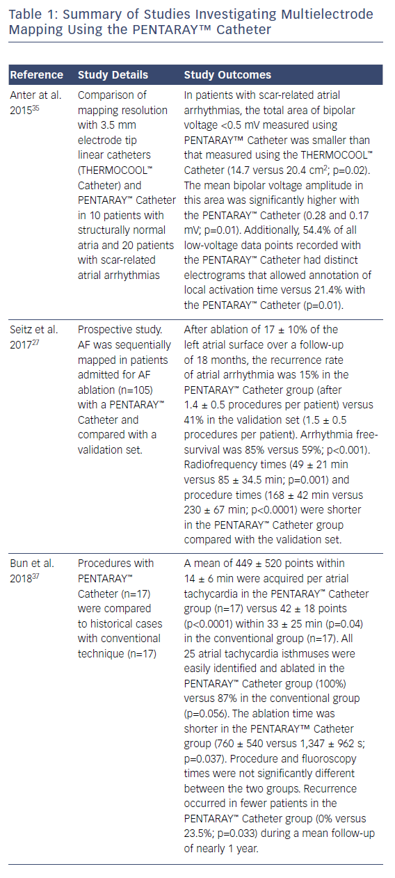
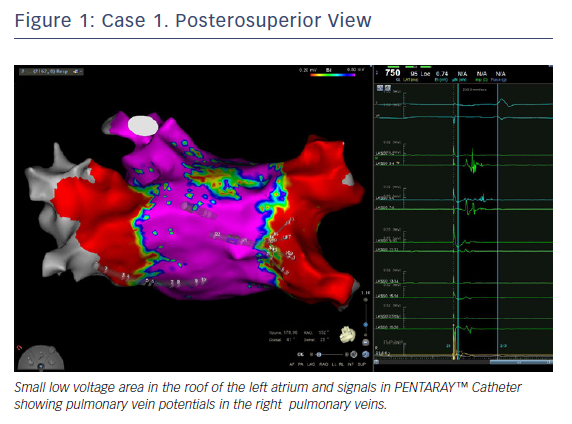
In this case, the left PVs had a common trunk that had been isolated since the prior procedure in 2015. There was PV re-conduction to the right superior pulmonary vein (RSPV) and right inferior pulmonary vein (RIPV), and there was a patchy scar area in the roof (Figures 1 and 2). Both the voltage map and conventional signals in the PENTARAY™ Catheter clearly showed the reconnection to the right PV. Only PVI was done in this case and the small patchy scar area was not targeted.
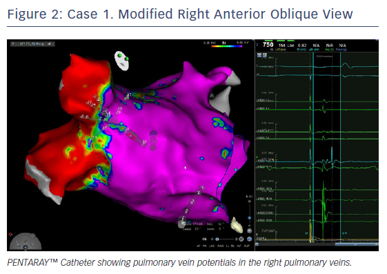
Ablation was done with point by point with the THERMOCOOL SMARTTOUCH® Catheter (Biosense Webster), using CARTO VISITAG™ for tagging ablation points. A tag index of 550 was used for the anterior wall and 400 for the posterior wall. Interlesion distance was <6 mm. A new voltage map was made after the PVI. This showed low voltage (<0.2 mV) distal to the ablation line around the right PVs (Figure 3). When checking for PV isolation after the ablation, it is important to rotate the PENTARAY™ Catheter around the PV ostium and check for PV potentials and to avoid using just the voltage map. Furthermore it is very important to check for signals between the veins.
The CONFIDENSE™ Module uses impedance differences between blood pool and tissue (the TPI) to determine that the PENTARAY™ Catheter has contact with the atrial wall. There will be oedema in the tissue immediately after ablation, which makes it more difficult for the CONFIDENSE™ Module to determine if there is contact. Sometimes the clinician may have problems collecting continuous points with the PENTARAY™ Catheter using the CONFIDENSE™ Module around ablation lines straight after the ablation. If this problem is encountered, reset the TPI after ablation.
The voltage map will be used to discuss the further ablation strategy with the patient if they are not helped by PVI alone. In the case of a redo, a modified roof line in the shape of a V can be drawn between the right PV and the left common trunk to address the low-voltage area in the roof.
Without the high density map there would have been no additional information about fibrosis and dispersion areas. Moreover, the PENTARAY™ Catheter allowed fast mapping without any additional difficulties on entry to the pulmonary vein (especially the right inferior). In addition, checking the vein isolation using the PENTARAY™ Catheter is faster and more reproducible compared with the Lasso catheter. These factors are less important in paroxysmal AF, but in persistent AF time and information are crucial.
Case Study 2
The patient was a 47-year-old woman with lone persistent AF (long-lasting; >6 months). The catheters used were Deflectable 10 electrodes F curve, PENTARAY™ Catheter F curve 2-6-2 mm and THERMOCOOL SMARTTOUCH® Catheter F curve, with a single transseptal puncture.
After the transseptal puncture, a counter-clockwise torsion was made through the sheath in order to reach the RSPV with the PENTARAY™ Catheter. The PENTARAY™ Catheter was pushed deep inside the vein until no signal was recorded. Then, in order to define the ostium of the vein, the catheter was pulled back with light curve and slowly turned around the vein. Respiratory gating was done at this point.
The inferior pulmonary vein was reached by pulling out the catheter from the RSPV, by maintaining a counter clockwise torsion and then by bending it. The ostium of the RIPV was identified by performing the same manoeuvres described for RSPV.
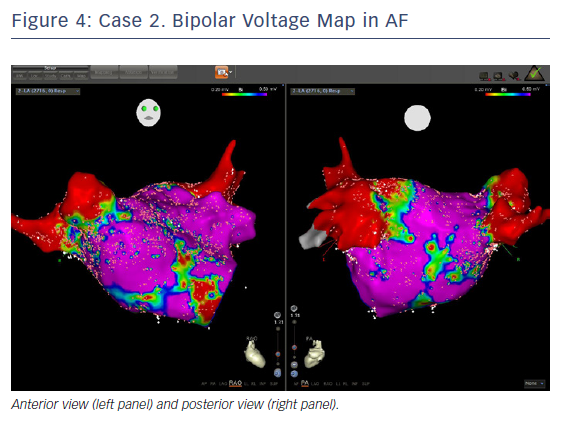
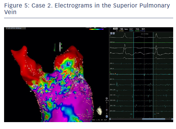
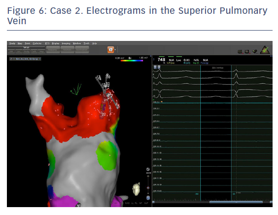
The entire mapping phase was performed in AF with the aid of CARTO™ 3 System V6 CONFIDENSE™ Module (number of points acquired: 2,716; bipolar voltage map 0.2–0.5 mV; with filters and settings in the CONFIDENSE™ Module set to the following: TPI on, LAT stability off, position stability 4–6 mm; Figure 4). Mapping time was 18 minutes. Low-voltage areas were delineated based on a bipolar voltage of <0.5 mV during AF (determined as the maximum bipolar voltage of two consecutive AF beats), according to the current literature.6,29,39–41 In this case, few areas of bipolar <0.5 mV were detected, and the high signal resolution of the PENTARAY™ Catheter allowed the identification of spatio-temporal dispersion areas.42,43 Most of the dispersion regions were found around the RSPV (Figures 5 and 6). By adding bipolar mapping with dispersion signals information, the adopted ablation strategy was PVI only without any additional areas or line.
A point-by-point ablation (interlesion distance 6 mm, 35 W) was started from the RSPV. CARTO VISITAG Module with Ablation Index (AI) was 500 in the anterior wall and 380 in the posterior wall (300 AI when oesophageal injury suspected). Sinus rhythm was restored during RF application in the roof of the RSPV. Right and left veins were successfully isolated at the end of the procedure.
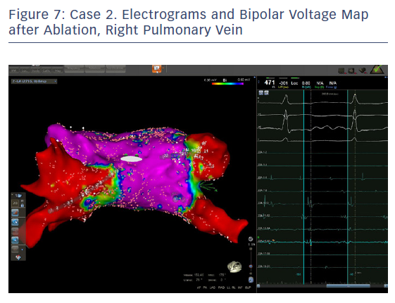
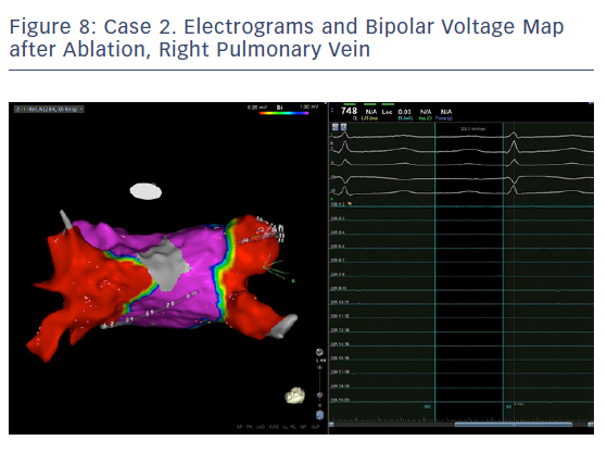
In order to check isolation, a new bipolar map was produced using the PENTARAY™ Catheter using higher voltage values (1mv-0,2), focusing on the ostium of each PV. This proved the absence of gaps around the lesion lines (Figures 7 and 8). In addition, by selecting the spline in contact with the tissue, the exit block was verified by stimulating within the line of the lesion. The entrance block was confirmed by stimulating the proximal CS electrodes.
The PENTARAY™ Catheter creates an anatomy of the LA that is closer to the true anatomy. This makes it easier and safer to plan and perform the ablation lines. A multipolar catheter with smaller electrodes with closer interelectrode spacing facilitates detection of gaps, facilitating a safer and more effective PVI.
The PENTARAY™ Catheter is not better just for scar-related AF but also in all types of AF compared with a standard circular (Lasso) catheter. An electrophysiologist who doubts substrate-based ablation and wants to perform a standard PVI could also benefit from using the PENTARAY™ Catheter instead of a Lasso catheter. Substrate-based ablation has a Class IIB recommendation while PVI has a Class IA. PENTARAY™ Catheter creates a better anatomy and is better for mapping gaps. Therefore it will still confer advantages even if the operator chooses only to perform a PVI.
Case Study 3
The patient was a 65-year-old woman with lone persistent AF since 2012. She had no structural heart disease, normal EF and a dilated LA (28 cm2). Treatment with flecainide failed and was replaced by amiodarone. This was followed by two electrical cardioversions, the last one in January 2018 with fast recurrence. Ablation was performed in July 2018. Catheters used were: deflectable 10 electrodes F curve in CS, PENTARAY™ Catheter F curve 2-6-2 mm, THERMOCOOL SMARTTOUCH® Catheter F curve, with a single transseptal puncture with general anaesthesia. After the transseptal puncture, the guidewire was pushed into the LSPV, the sheath advanced in the vein or close (note: ensure this is not moved into the LAA) and the PENTARAY™ Catheter introduced deep inside the vein until no signal was recorded. CS CL was 170 ms with fragmented signals on the proximal side, while the LAA CL was 160 ms.
In order to define the ostium of the vein, the catheter was pulled back with a clockwise rotation to define the posterior border of the vein and counter clockwise rotation for the anterior part of the vein. When the catheter jumped into the LAA, the points were annotated as ostium or ridge. This manoeuvre was repeated for the anterior part of the LSPV and left inferior pulmonary vein (LIPV), and for the inter-venous space. When the PENTARAY™ Catheter jumped from the LSPV to the LIPV (pullback and clockwise rotation), there was rotation around the veins for a complete anatomy. Real anatomy was merged on the table with the CT scan (using CARTO-Merge) after left PV and LAA reconstruction, with variable transparency after reconstruction. Delimitation of the ridge between LAA and anterior part of the left PVs is crucial for isolation of the left PVs. The same importance is given for accurate mapping and ablation of the posterior side of the LAA when signals are very fragmented. After ridge definition, careful reconstruction of the LAA anatomy with PENTARAY™ Catheter, anterior and posterior side, and annotation of the fast and/or fragmented signals (target for ablation after PVI) was performed.
The PENTARAY™ Catheter was rotated clockwise on the posterior wall with RSPV catheterisation. This was followed by the same manoeuvres as the left side for ostium delimitation, then a clockwise rotation for the septal side of the RSPV and anterior side of LA, with manual annotation of FS and gradient area (ablation target after PVI). It was pulled back slowly, with counterclockwise rotation for RIPV catheterisation and rotation to complete anatomy.
To obtain the LA anatomy, it is very important to map the inferior side in front of the CS. We found very fragmented signals (annotation) with advanced sheath and the PENTARAY™ Catheter curved into the inferior direction and moved from the mitral annulus to the inferior part of the RIPV. Careful mapping of the mitral isthmus (normal voltage, so no ablation) is required. It is important to avoid ablation, especially in this area, if there is no FS and normal voltage, and not to induce a slow conduction to induce a perimitral flutter – this is difficult to ablate, especially to achieve a blocked line.
The voltage map was performed with the PENTARAY™ Catheter at the same time as LA and PV reconstruction. TPI was always used, with filters and settings in the CONFIDENSE™ Module as follows: TPI on; CL range ± 5 ms; position stability 4 mm; and density 1 mm. Bipolar voltage threshold was set to 0.2–0.5 mV for diseased areas and the colour fill threshold was set to 5–6 mm. PVI was carried out with the SmartTouch SF contact force catheter F curve, point-by-point ablation with an ablation index of 450 on anterior part and 350 posterior part (oesophageal temperature monitoring); 40 W anterior part, 25–30 W left posterior (oesophageal temperature monitoring and RF stopped if temperature increased by 1°C), 30 W right posterior. To check PVI, check that no signals are recorded inside the PVs, and check again in sinus rhythm with exit block by pacing. LA mapping time was 10 minutes and total RF ablation time for PVI was 12 minutes. There were short RF applications (12–15 seconds/RF application with 10–20 g contact force) in order to reach the targeted ablation index. There was no modification of LAA CL after PVI.
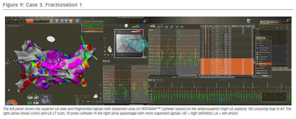
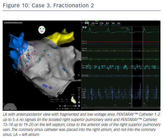
LA voltage map with high-definition colouring (3,129 points) was performed, with ablation of four areas on fragmented and low-voltage areas – septum anterior to the LAA (Figures 9 and 10), inferior LA, especially below the RIPV in front of the proximal CS, posterior between inferiors PVs, and posterior to the mitral isthmus with AF organisation into this latter area (220 ms). However, after 2 minutes there was further AF, although CL was slower (190–200 ms, variable), and there were still multiple sources for the AF. Ablation time for the four zones was 13 minutes RF (35–40 W septum, 30 W posterior [under oesophageal temperature monitoring] and 35 W inferior LA). The surface area of the LA for the four zones was 36 cm2 (13% of total LA area) and LA volume was 200 ml.
A voltage right atrium map with high-definition colouring (974 points) was performed after LA ablation without low-voltage areas and longer CL (245 ms), showing there were no criteria for ablation. This was the same for the epicardial coronary sinus (230 ms). The sinus rhythm was obtained by electrical cardioversion. The procedure duration was 110 minutes and fluoroscopy time 45 seconds (0 after transseptal puncture). The PENTARAY™ Catheter was very useful to precisely quantify the surface of the low-voltage area and target inside the rapid and fragmented signals in order to modify the LA substrate in this case of persistent AF.
Summary and Concluding Remarks
Catheter ablation for the treatment of persistent AF is associated with suboptimal outcomes, largely because of the presence of scar tissue. AF recurrence is frequently reported, and patients often undergo repeat ablations after conventional PVI procedures. Substrate-based modification via targeting areas of scarring areas of the LA has therefore emerged as a promising therapeutic strategy to maximise long-term freedom from AF. In order to optimise accuracy and reproducibility of scar maps, there is a need for standardised protocols and uniform cutoffs for scar detection.
As illustrated by the case studies, the PENTARAY™ mapping Catheter offers high spatiotemporal resolution, and ablations performed using the PENTARAY™ Catheter have been associated with shorter procedure times and fewer recurrences of AF. While the PENTARAY™ Catheter has proven useful in terms of finding abnormal areas, there remains at present no tool to facilitate our understanding of the mechanism of low-voltage areas and the optimal methods of treatment of these areas. It is hoped that the CARTOFinder will help us to improve our knowledge of persistent AF. In summary, while larger studies are needed, clinical evidence to date suggests that the use of the PENTARAY™ Catheter may facilitate successful ablation of scar-related AF.